Performing measurements
Intro
Certain code sequences require you to perform measurements on the screen. CAM-I provides additional support to easily perform these measurements using overlays on the video screen and when available, also on lidar cross-section and roll-out visualizations.
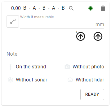
Whenever you can perform a measurement, there will be a button in front of the input field of the observation. This will allow you to measure deformations, sizes and angles. Some of these measurements can be done 'as is', but others require some calibration of the camera if the crawler can't report the distance to the wall (usually measured with a laser).
Furthermore, you can always activate a lidar-measurement tool at any time, nomatter if there is an observation selected or not.
Depth

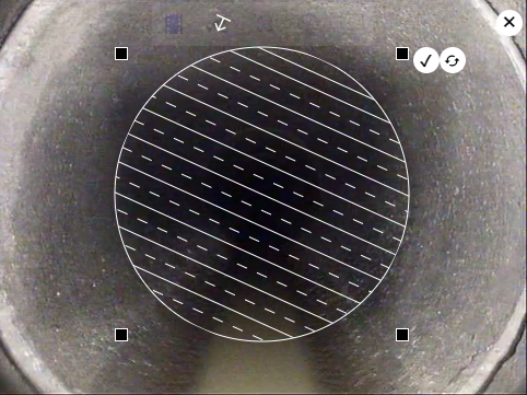
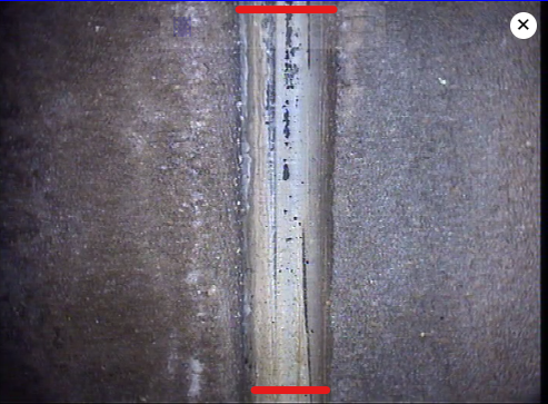
Some code sequences, like those that record the presence of water, require you to enter the depth or vertical level. This value can be measured using the depth overlay which shows an image containing a bunch of horizontal lines.
- in the upper-right corner of the video image is an 'x' sign which you can use to remove the measuring tool from the screen and abort the operation.
- You can drag the image around to position it correctly.
- In the upper-right corner of the image, are 2 extra icons.
- The right most icon is a toggle that selects the function of the squares in the corners of the overlay.
- By default, you are in resize mode, so you can use the squares to resize the image and make it fit the size of the strand. The icon will display 2 circular arrow to indicate that you will switch to rotate mode.
- In rotate mode, you can use the squares to turn the overlay left or right in case the camera isn't centered properly or when you are measuring something against the wall. The icon will show a diagonal arrow, indicating that you will switch back to resize mode if you click on it.
- The left icon, representing a 'V', fixes the position of the overlay. Once you click on this icon, you can no longer move it around, but only click on it, to indicate the position of the water level.
- The right most icon is a toggle that selects the function of the squares in the corners of the overlay.
This measuring mode doesn't require any calibration or extra input values, so it is always available.
deformation

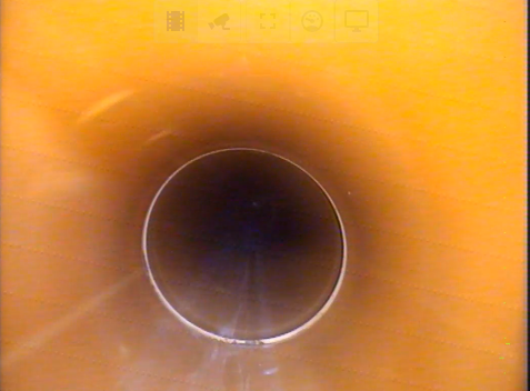
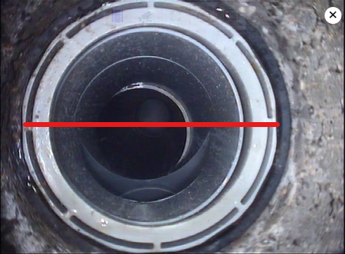
Sometimes, strands can get deformed, for instance it could be crushed by the weight of what's on top. Plastic strands can be especially prawn to this. To measure the amount of deformation on a strand, you can use the deformation-measuring tool.
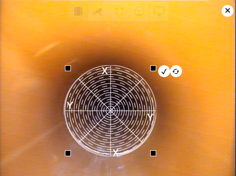
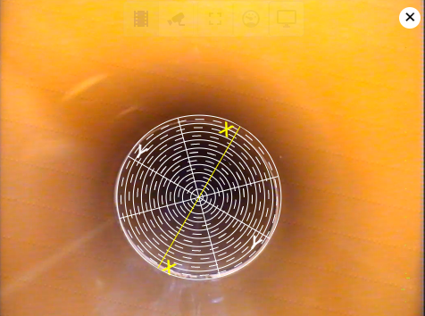
As an example, see the first image in the upper-left corner, which contains a small deformation at about 2 o clock. When you activate the tool, you will get the bulls-eye target that you see in the picture on the right side.
In the first stage, you can resize, move and rotate the overlay again so that it properly fits on top of what you want to measure. Make certain that you rotate the overlay so that either the x or y axis is over the most malformed point, like in the bottom image to the left.
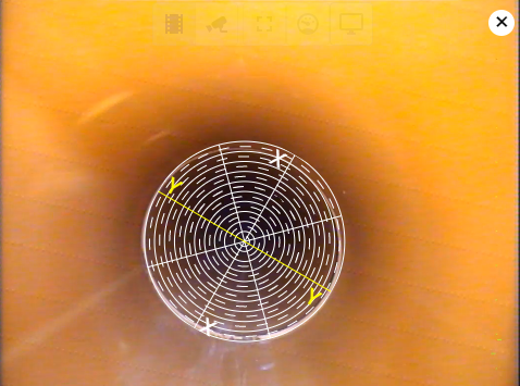
Once the overlay is in position, you can click on the checkbox in the upper right corner of the overlay. This will activate the measurement stage, which is a 2 stage process. The application will highlight the axis upon which the measurement should be done in each stage. First is the x axis, then the y axis. You should click where the x-axis intersects with the circular reference line that matches the underlying deformation. When you have clicked on both axis, the measurement is complete and the application can calculate the value.
freeform

Certain code sequences need a % value, usually to indicate the amount that the strand is blocked. for instance, if there is a root system, you need to specify how big it is.
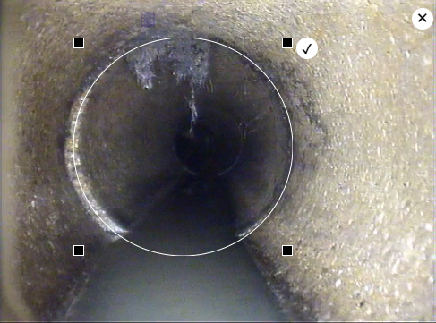
The freeform overlay tool provides an easy way to calculate this value. When this tool is first shown on the video, you will see a shape surrounded with 4 squares that you can use to resize it. You can also drag the shape around so that you can put it on top of the strand like in the image below.
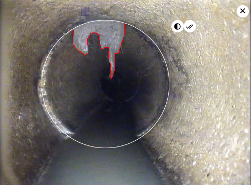
Once you have positioned and resized the shape properly, you can click on the checkbox icon in the right-upper corner. This will switch the tool to the measuring stage. Now, you can trace over the edge of the object that you want to measure, like in the image below, to the right. Use the left-most icon in the upper-right corner, a circle that is half-filled, to invert your selection. To restart the drawing, simply start retracing again. Once you are happy with the drawing, click on the double-checkbox, in the upper-right corner to calculate the value.
This measuring mode doesn't require any calibration or extra input values, so it is always available.
If you have a lidar at your disposal, this measurement can be done automatically from the lidar cros-section view. When activated, this value will update automatically every second.
size

Sometimes you just need to measure how big something is, like the diameter of a side connection. You can do this with the size measuring tool on the screen or with the lidar, when available.
screen
When on the screen in this mode, you can draw a line on the video. The application will calculate the distance of the line, as if it were on the wall of the strand.
For this to work, the system will need some extra information, provided during calibration of the camera. Although no extra hardware is required to perform this type of measurement, accuracy can greatly be improved with some form of measuring the distance to the wall. From most accurate, to least accurate, there are:
- a laser-distance meter, usually built into the crawler
- 2 parallel lasers, at a fixed distance of each other, no matter the distance
- 2, non parallel lasers, going apart from each other
- no distance measurements, in which case the system relies on the diameter of the strand. Note that changes in the diameter during recording are taken into account while performing size measurements.
lidar
If you have a lidar system, this measurement can be done automatically, both on the cross-section view as well as on the rollout. Though there is a small difference between both types of measurement. This can best be explained with a picture:
The cross-section (above, to the left) will measure in a strait line between 2 points, not taking the curveture of the strand into account. The rollout on the other hand will measure along the curviture of the strand. This wont give much of a difference, but with larger surfaces combined with the accuracy of some lidars, this can be noticable.
To perform this measurement on the cross-section view, click on the first point you want to start measuring from (right-most point), than move
to left (counter clock wise) and select the second point. While moving, a triangle will be drawn in red, showing your current selection. The
value will also be displayed in the upper right corner.
To make a fresh selection, simply click on the a new first point and move to / select the second.
On the rollout view, you can simply draw a strait line between the 2 points you want to measure.
angle

This measurement tool allows you to measure the total angle deviation found in joints. These should ideally be perfectly parallel. When they aren't and there is a visual deviation, it has to be noted in an observation.
screen
When activated, you will be able to draw 2 lines on the screen as shown in the image below. The system will use this information to calculate the deviation angle.
Note: this measurement tool might require calibration.
lidar
If you have a lidar, you can do a similar measurement on the rollout view. Here, the lines need to be drawn in parallel with the lines that you see on the lidar data (which should make it easier and more accurate). The first click will select the starting point of the first line. select the endpoint of the first line with a second click. A third click will define the start of the second line. Close it with a final click. To redraw the selection, click again to select the new first point of the first line.
calibrating the camera
To convert pixels into a distance, most often, the camera will need some sort of calibration. Usually, this is a 2 step process for the minimum and maximum distances, but if you have a laser measurement system where the lasers aren't strictly parallel, the calibration has a few extra steps.
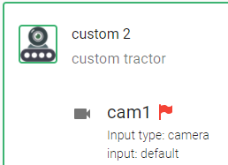
To calibrate your camera for screen measurements, go the settings page and select the tab 'hardware'. Go the configuration for which you want to calibrate the camera (doesn't have to be active) and click on the flag next to the camera. The color of the flag indicates the state of the calibration:
- red: not yet (fully) calibrated
- green: the calibration is ok
When you click on the flag, a 4 or 5 step wizard will start. 5 in case of a laser system with 2 lasers that aren't parallel.
The first step is just a small explanation of the process

In the second step, a measurement is done for the smallest possible distance to the wall. 2 values are needed:
- The length of the line you are going to trace. If you have 2 lasers, there is no need for a line, but instead, you will have to specify the actual distance on the wall between the 2 dots.
- The distance between camera and the wall, in the bottom field 'distance wall-camera'.
Finally, click on the 'measure' icon in front of the 'distance-to-wall' field. This will open the camera feed.
- If you have 2 lasers, the dots will be discovered automatically and the location of the dots will be indicated. When the result is good (it might take a little calibration), click on 'ok'.
- When your system doesn't have lasers, you will have to trace a line on the screen that you drew on the wall (or a paper on the wall).
The 3th step is very similar to the second, accept that the process is now repeated for the maximum distance between the camera and the wall at which you would like to perform measurements.
When you have to trace a line for the calibration, it can be very useful to use a longer line at the maximum distance compared to the one used at the minimum distance.for non-parallel laser calibration, an extra 4th step is included. At every 10cm between the minimum and maximum distances (between wall and camera), the system needs to measure the distance between the laser dots. Most of this process is automatic, but the camera feed has to be opened for every measurement and before the dots are detected, some time might pass due to auto-calibration of the dot-detection algorithm.
the last step is again informative to let you know we are ready. You can close the dialog now and the calibration will be saved.